Saturday, February 17, 2018
Tuesday, January 02, 2018
Wednesday, October 04, 2017
Sunday, July 16, 2017
Sunday, February 19, 2017
Saturday, October 29, 2016
Thursday, October 27, 2016
Thursday, May 26, 2016
Thursday, November 05, 2015
Thursday, November 01, 2012
Dave's R/C Friendship Sloop model Florida

Another of Dave Mainwaring's, Friendship Sloops:
Florida,
R/C fiberglass, built in 1970
R/C model Friendship Sloop

Another of Dave Mainwaring's R/C Friendship Sloops,
medium size models make nice display models
However they are tender on windy days.
Friday, June 17, 2011
Beautiful wooden ship models

Date: Tue, 17 Jun 2008 20:58:30 +0200
From: Michael Czytko
To: mainwaring
Subject: Contribution to Blog on ship modelling
I had a look at Building Model Boats and Ships blog
I would be glad if you could add my article as a contribution.
Best regards
Michael Czytko
High resolution photographs of historic ship models
Tall ships are very impressive when you have a chance to meet one at sea. Scale models of tall sailing ships, too, can be as fascinating as the original ship. The elegance of these ships can be beautifully represented by models, and one can very much enjoy looking at the fine craftsmanship of their makers. That is why many people have made sailing ship modelling their hobby.
To make a fine and true scale model one needs plans of the original ship and books or other literature on historic details of naval technology at that time. Exact plans of many famous ships can be bought from museums like the Musee de la Marine in Paris or well known ship model builders like Jean Boudriot. Literature on ship modelling and history of naval technology by well known and recognized authors is readily available, too. But high in desire are high resolution photos of ship models, as they are a fast means to decide how to tackle a specific problem or answering detail questions on rigging and planking.
There are only few websites that show such photos. On this ship model webpage (http://www.modelships.de/eng/) one can find more than 2000 high resolution photographs of finely built ship models, like a carvel-built Hanseatic League ship of 1470, the Santa Maria of Christopher Columbus of 1492, Sir Francis Drake’s Golden Hind in 1577, the Sovereign of the Seas of 1637, the French Soleil Royal of 1669, an 18th century Arabian chebec, the frigate USS Constitution of 1797 and Admiral Nelson’s HMS Victory of 1805. Each ship model is shown in 10 – 40 photos of 600 * 450 pixels and in high resolution of 6 – 12 megapixels.
Ship model makers will love this site, whether they look for historic details or just for information and suggestions when building their own ship model.
Wednesday, April 22, 2009
Turbulators by Lester Gilbert {Turbulator on keel fin}
Following the theoretical analysis of the boundary layer and the roughness needed to stimulate BL flow transition, I've experimented with a simple turbulator (turbulence stimulator) on my Ikon fin. Until recently, I used a SAILSetc fin with 7% thickness ratio, and tried turbulators before without really noticing much difference. I've now fitted a new fin with 6% thickness ratio, and wondered if the thinner fin might be somewhat more prone to early stall while beating. So I tried a turbulator again.
Turbulator on fin
The first photo shows the general position of the turbulator strip at 70% of chord, the position Graham Bantock recommended as being appropriate for the foil section he uses. The second photo shows a detail view of the strip, cut with pinking scissors to give a zig-zag about 1.5 mm wide. The strip illustrated is about .010" thick, approximately .25 mm. This is pretty much the minimum thickness needed towards the fin tip according to the roughness spreadsheet, and may be a little too thin for the chord at the fin root. I have plans to experiment with a slightly thicker turbulator on the upper part of the fin. The line drawn on the fin marks the 70% chord position, so the turbulator starts its stimulation with its peaks placed along this line. In an earlier trial I had the turbulator at 50% of chord, and this seemed to give rather more of a drag penalty without a noticeable improvement in lift or postponement of stall.
Turbulator detail
I've found the results to be quite pleasing. The turbulator doesn't seem to have hurt performance very much on the run; that is, the drag penalty seems acceptable. But I feel that the boat is now more effective on the wind, more willing to point. So the fin seems able to either generate a little more lift than before, or to do it more efficiently. Also, the boat doesn't seem quite so prone to stalling during low speed manoeuvres, like creeping towards the starting line with sails sheeted out and not too much way.
2006-07-11
©2008 Lester Gilbert

Monday, December 01, 2008
Pat's Hacks, servo motor conversions
Thank Pat Matthews for sharing the following post on servo hacks!
Servos are wonderful little devices! Not only do they provide an inexpensive way to activate mechanical linkages through radio control, but they can be hacked to provide inexpensive drive units for small boats and cars with their self-contained motors and electronic speed controls (ESC's), and they can serve as part of a simple on/off power control switch.

Basic servos can be found for less than $10
A servo is a little gear-motor, ESC, and a position sensing device in one package. Rip the guts out of the case, and you'll have:
a) A lead from the Rx… it carries +5 volts, ground, and a signal wire.
b) A circuit board.
c) A small 5v motor, which may be soldered directly to the circuit board.
d) A pile of gears connecting the motor to the servo output. Bin these.
e) A potentiometer (pot, or variable resistor) connected to the circuit board with 3 leads, and mechanically connected to the servo output.
 Step 1: A few screws loose, and things start to open up.
 Step 2: Pressing on the two shafts popped the board out of the case. Don't pry directly on the board.
 Step 3: Using desoldering braid to wick off the solder, makes it easier to pull off the motor.
 Loose parts.
Hack 1: Going Pot Free
First trick in hacking a servo: Disconnect the pot from the servo output. Normally, as the pot moves with the servo output, it produces a varying voltage which is read by the circuit board, telling the servo that the output has moved to the desired position (or not). See Schematic 1. When you disconnect this little knob from the gear train and the servo output, leaving it in it's centered position, and then command servo movement at the radio, the circuit board never detects any movement, and thus keeps telling the motor to run.
So now center the stick, servo is happy, goes nowhere; forward stick, and the motor kicks in and just keeps buzzing; reverse stick, ditto the other way. You'll want to put a drop of glue on the pot to keep it from drifting.
Hack 1a: If the Pot itself doesn't suit you, you can replace it with a pair of 2.2k ohm resistors- both tied to the center tap's lead, opposite ends of the resistors to the pot's "outer" leads.

Another nice feature- most servos have a soft start, which means that a little bit of stick will give part throttle… other than that, it's pretty much off/on.

Hack 2: Motor Swapping
Next hack: The little motors that comes with servos may not suit you… they have tiny little short shafts. Any small 6v toy motor will do instead, as long as you don't load it heavily- the servo's ESC isn't designed to deliver much current! If the motor is connected to the circuit board with wires, no problem to swap them. If the motor is soldered directly to the board, you'll need to work a little more carefully. You can get "solder braid" from Radio Shack- braided copper wire that you heat with a soldering iron while pressing onto the board's soldered joint. The braid sucks up the solder, and you can pull the motor loose much more easily.
If you decide to keep the servo motor, no problem. You can leave the motor on the board- that's what I did on my plastic landing craft. And you can get tiny little plastic u-joints to press onto various miniature shaft sizes, metric and English, from Northwest Shortlines- catalog page at http://www.nwsl.com/Catalog/cat-UJoint.pdf
 |  |
| Servo motor still attached to board. Motor can is pressed into plastic structure. | Twin drive in landing craft. |
 |  |
| Servo motor set in Revell Trawler | Close-up of NWSL U-Joint on servo motor's 1.5mm shaft. "Horn" is sized for 1/16" prop shaft, which is only slightly larger than 1.5mm. |

Pat's site: http://www.geocities.com/patsmodels/servo/
Thursday, November 06, 2008
1/16 and 1/8 plywood
They also carry Baltic Birch plywood: 1/16'' and 1/8''
http://www.boulterplywood.com
toll free at 888 - 9 LUMBER. (888) - 958 - 6237
or Email: chris@boulterplywood.com
--
Okoume Plywood Information:
1.Face / back: okoume Core: poplar, hardwood, pine ,
2.Size: 1,220 x 2,440mm, 1,250mm x 2,500mm, 915 x 1,830mm or as requested
3.Thickness: 3.5mm-30mm
4.Glue: WBP, MR, E1, E2
--
Wood Properties of Okoume from
http://www.connectedlines.com/wood/wood47.htm
Okoume Alternative Name 1
Gaboon
Okoume Available as Veneer
Yes
Okoume Bending Strength
Moderate
Okoume Blunting of Tool Blades
Moderate to Severe
Okoume Botanical Name
Aucoumea klaineana
Okoume Carving
Average to somewhat difficult to carve
Okoume Clear Finish or Varnish
Fair
Okoume Color of Wood
Pink Brown
Okoume Density
Low
Okoume Drilling
Fair or Satisfactory
Okoume Gluing
Good
Okoume Grain
Mostly Straight
Okoume Hand Tooling
Average
Okoume Hardness
Soft, easy to dent
Okoume Hardwood or Softwood
Hardwood
Okoume Harmful Properties
Non Toxic
Okoume Mortising
Fair or satisfactory
Okoume Nail Holding
Good- Nails are fairly difficult to pull out
Okoume Nailing
Fair - may require pre-drilled pilot hole especially near ends
Okoume Natural Durability
Non-durable
Okoume Polishing
Good
Okoume Sanding
Fair or satisfactory
Okoume Sawing
Moderate cutting resistance
Okoume Screw Holding
Good - Fairly difficult to remove screws
Okoume Screwing
Fair - May require pre-drilled pilot holes especially near ends
Okoume Size of Pores
Insufficient Data Available
Okoume Staining
Fair - May stain unevenly or change colors
Okoume Steam Bending
Poor
Okoume Stiffness
Low
Okoume Surface Preparation for Finishing
No
Okoume Texture of the Wood
Intermediate
Okoume Weight
Light
Okoume Wood Defects
Check (or split,) warp
Saturday, November 01, 2008
Friendship Sloop - Pemiquid


Billy Hogan with his Friendship Sloop.
January 2005
kit was circa 1971 from Dave Mainwaring
They make a beautiful R/C sailing model

Jonesport model under construction, , 42 inch glass hull
42in_lb_model_10.jpg
Posted by target='ext'>Hello
42in_lb_model_03.jpg
Posted by Hello
Dave Mainwaring, 42 inch model under construction
Fibre Glast Developments _ Estimating Materials
1) Begin by calculating the surface area of the project. Estimate irregular shapes by measuring the approximate sized rectangles necessary to contain the tapered areas. Multiply the length times the width for each rectangle, and then add all of individual rectangles together to get the total surface area of the part. If the calculation is in square feet, divide by 9 to get square yards.
2) Make a list of each type of reinforcement being considered for the lamination. Multiply the square yards calculated above times the ounce weight of the fabric. This is the total weight of one layer of that material. It is also the amount of resin required to saturate it. When this is known for two or three different types of materials, it is possible to calculate the weight and cost of a laminate constructed from any combination of these fabrics. To convert the ounce weight to pounds, divide by 16. Those inexperienced in saturating fiberglass tend to use far too much resin. A well saturated laminate is uniformly translucent, without milky appearing dry spots, but for the sake of weight and cost, has little excess resin in it."
The Fundamentals of Fiberglass - Fibre Glass Developments
Accurate material estimates are necessary for two reasons.First, they obviously are needed for proper ordering, material stocking, and bidding of projects. More importantly though, estimates offer the opportunity to calculate the weight or cost of the part using a variety of laminating schedules before beginning to build.
Unlike estimating coverage when painting, resin usage will vary depending on the type of reinforcement being used. The heavier the fabric, the more resin it will take to wet it out. A good hand laminate consists of about 50% fabric and 50% resin by weight. For example, if an application requires 3 sq yds of a 4 oz/sq yd fabric (total fabric weight = 12 ounces), 12 oz of resin will also be needed. However, if 3 yards of 10 oz/sq yd fabric is chosen (total fabric weight = 30 ounces), 30 oz. of resin will be needed.
Glass mat requires a minimum of 2 ounces of resin for each ounce of mat. Therefore, it the application calls for 20 sq feet of 1-1/2 oz/sq ft mat, it will require a minimum of 60 ounces of resin. Remember that mat is specified in ounces per square foot, where fabrics are specified in ounces per square yard. 1-1/2 oz/ sq ft chopped mat actually weighs 13.5 oz/ sq yd!
Since there are so many possible combinations of materials, one should calculate the weight and cost of a single layer using a variety of reinforcements. These can then be added or subtracted form the theoretical laminate until the design properties are achieved."
Wednesday, October 08, 2008
The following are a compilation of Lester Gilbert's materials, materials of others"
Lester Gilbert is at Learning Societies Lab, University of Southampton, Southampton SO17 1BJ, United Kingdom he may be reached by email at lg11@soton.ac

Adjusting the wind tunnel model
Lester Gilbert on understanding of sail making for model sail boats
For anyone interested in sailmaking, I've just finished editing Larry Robinson's "Making Model Yacht Sails" (part 1 only) booklet and have published it as an "international" edition. I've done this, not to get rich ('cos this isn't going to happen to either me or Larry or anyone else connected with this enterprise!), but because I've spoken to a lot of sailors who want to make sails but don't know the "right" techniques, and who are being misled by incorrect accounts of how this might be done.
A sail block
(Illustration from Larry Robinson's "Making Model Yacht Sails")
From my understanding of sail making, there are two ideas I want to contradict.
The first idea is that you can make sails by accurately cutting a curve on a panel, and then attaching it (stitching, gluing) to another panel. Well, while you might be able to cut a good curve some of the time, your fingers just don't have laser accuracy in them to stick A to B and you'll hardly ever obtain reproducible or reliable results. (It might be possible to butt-join the curved edge to another curved edge with a little more reliability, but this doesn't yield what the Equipment Rules of Sailing define to be a seam. Such a sail couldn't be used in sanctioned IOM competition, though it would be OK in a development class.)
The second idea is that you can drape your panels over a "camber board" and get a nice shape that way. Well, let me be clear about what I'm knocking here. I take a "camber board" to be a length of curved surface, where the curve is like the surface of a cylinder. In this case, your panelled sail will have exactly the same shape as a single un-panelled sail and, if you wanted a three-dimensional shape, you've wasted your time (though the result certainly looks the part).
Larry's booklet is the only source I know which carefully explains the use and construction of a sail block. I am sure that this is really the only way (in your garage, please, not in some specialist workshop!) to make professional sails, to obtain reliable and reproducible three-dimensional shaping, and to be able to tweak and change your shaping as you learn about the whole business.
(Warning: Y'all should know I have ten thumbs and have never made a sail yet. What I have done carefully is to watch and talk to those who do, both professionally and as home builders, and measure the results. Making Larry's booklet available internationally is my way of telling you what I've learned.)
Bob Wells will be able to ship this within the USA, and I expect that it will also be available from Don Ginthner at GBMY. For worldwide sales, contact SAILSetc. Bob Wells' e-mail is "bob" at "islandinet.com", GBMY is "rcsailing" at "gbmy.com", and SAILSetc can be contacted through "sales" at "sailsetc.com".
I've attempted an analysis of how blocks work on a new page, Sail blocks analysis, and have a new spreadsheet there to help.
©2008 Lester Gilbert
2006-07-11
Lester Gilbert on Sail twist:
http://www.onemetre.net/Design/Twist/twist.htm
Given a wind gradient, and given the way the jib deflects the wind over the main to put it into a header, what sort of twist needs to be applied to the sails to optimise their entry angles?
I've come up with a second twist spreadsheet (about 27kb), which takes the earlier "gradient" and "apparent wind" spreadsheets and combines them with new material on "equivalent angle of attack" of arc-section plates, and on downwash. It's pretty! If you'd like to continue, I'd suggest printing this page, then downloading and running the spreadsheet. You'll need to cross-reference quite often.
UPDATE: A fourth version of the spreadsheet, now twist & downwash, here.
The first part of the spreadsheet allows you to specify the sailing conditions (wind strength, wave size, bearing, boat speed -- see the wind gradient and apparent wind pages for more details) and your boat setup (sail chords, draft, max draft location -- see the entry and exit page for more details). Then the interesting stuff begins.
We can start by noting that the red lines represent the "entry" angle of the luff to the wind, and the blue lines represent the "exit" angles. If we assume our sails have an arc-of-circle cross-section (yeah, I know, not a wonderful assumption, but it'll do to highlight the main points), then the entry and exit angles for a sail with max draft at 50% of chord are the same and are equal to 4*ArcTan(draft%). If the sail has max draft at another location, my spreadsheet breaks the arc down into two circular part-arcs, a forward part and an aft part, and calculates from there.
Now, the key at this point is that if these sails were rigid and were sailing off the left hand side of the page, they would generate a fair amount of lift, even though their angle of attack, measured at their chord, is zero degrees. I took a couple of interesting days digging through the NACA archives and I was rewarded with grand-daddy Prandtl (references in the spreadsheet) telling me that these sails develop the same amount of lift as a flat plate inclined at a tangent to the three-quarter chord. Now the tangent at three-quarter chord is none other than the line connecting the leech with the point of maximum draft, as illustrated by the green lines.
Entry, exit, attack for 10% draft Entry, exit, attack for 5% draft
Our 10% draft sail with max draft at 50% is running at an "equivalent" angle of attack of about 11.5 degrees. Move max draft forward some, to 40% say, and the "equivalent" angle of attack reduces slightly to about 9.5 degrees. Another way to look at these numbers is to say that the angle of attack of zero lift, which we'll need in a little while, is -11.5 and -9.5 degrees respectively. Of course, our sails get nowhere near negative angles of attack, they just luff out, but the general idea applies just as long as they are filled and driving. Here is another set of diagrams, but with a 5% draft sail.
Very roughly, take half the draft, and you end up taking pretty much half of all the other figures as well: entry, exit, and "equivalent" angle of attack/angle of attack at zero lift.
(As an aside, the NACA archive was fascinating. In about 15 years from 1905, ie from the Wright brothers, pretty much the whole of aeronautics had in principle been cracked. Prandtl could write a report in 1921 to which the rest of this century really just added footnotes. Amazing. Now we've been sailing for thousands of years, and there is nothing remotely comparable. Great! There is so much yet to know!)
OK. Now it's time to set our sail as a jib. We'll sheet it at 15 degrees to an apparent wind about 30 degrees off the bows, pretty much a standard sheeting angle for an IOM. The 10% draft sail illustrated (which has max draft at 40% of chord) seems to be unhappy at this sheeting angle. While it is making an acceptable "equivalent" angle of attack of about 22.5 degrees to the apparent wind, it is showing a very poor entry angle of around -13 degrees, and really could not hold this point of sailing at all. She'd luff and the boat would have to bear off. Also the exit angle shows the leech somewhat hooked over the centre line.
The 5% draft sail is showing a much better time of it, and can clearly point in the situation we are analysing. The "equivalent" angle of attack is less at about 17.5 degrees, and so the sail will develop less lift than the 10% draft, but the entry angle is nearly perfect -- exactly into the wind -- and the exit angle is good as well, just off the centre line.
Jib Main
So our 5% draft sail seems to be able to point 10 to 15 degrees higher than our 10% draft sail. But you knew that a flatter sail could point higher, didn't you? (In fact, the 5% sail can only point about 3 to 5 degrees higher than the 10% sail, not quite the full 10 or 15 we might have imagined. I'm still working on the reasons for this...) The old salts will tell us that a flat sail doesn't develop as much power, and they'd be right I guess. The maximum coefficient of lift of the 5% sail is about 1.1 at a nominal angle of attack of, say, 11 degrees to the apparent wind, while for the 10% sail it is more like 1.5 at an nominal angle of attack of about 15 degrees. The power developed by a sail is pretty much a direct function of its angle of attack (assuming, of course, the sail hasn't luffed or stalled). In a very real sense, the "only" purpose of a nicely shaped aerofoil (ie a sail) is to allow that aerofoil to achieve a maximum angle of attack. The "only" reason a flat plate isn't a wonderful sail is that it can't achieve much of a useful angle of attack. The 10% draft sail gives us about another 4 degrees of angle of attack over the 5% sail before she stalls, and hence gives us more power, but at the expense of not being able to point as high. On the reach, I'll take the 10% sail please. On the beat, though, pointing ability is more important, so give me the 5% sail.
We are not knocking 10% draft sails. We are just showing how the analysis so far, particularly from looking at the entry angle, indicates they can't point. I sailed a regatta a few years ago with a dog of a boat, and amazingly did well. The reason, I now realise, is that the course was a long rectangle, laid across the wind, so there was only one short beat but two long reaches. What I lost on the beat through lack of pointing I more than made up on the reach with a very full sail set.
Downwash
The next thing to do is to look at the situation with our mainsail. Before we do that, though, we have to remember that it is the downwash off the jib that puts the main into a header, and allows the main to be sheeted more closely to the centre line. So exactly how much is this downwash?
Another trip through the NACA archives revealed another grand-daddy, Munk (reference in spreadsheet), who trailed streamers behind a wing in a wind tunnel and measured the downwash. Thankfully, he wasn't shy about saying straight out that, over the centre section of the wing (we know vortices twirl up at the ends and mess things up there), downwash was pretty much the angle of attack divided by 1.8. Excellent. (If you've ever read any of these NACA reports, you'll know they are stuffed with the most excruciatingly difficult mathematics, whose real-world application to the job at hand is often dismissed with a wave of the hand and "It's obvious that..."!) Our jib at an "equivalent" angle of attack of 22 or so degrees to the wind will generate about 12 degrees of downwash. The main is now sailing into an apparent wind, 30 degrees at the jib, now deflected to about 18 degrees to the centre line. This was why we had to get straight about the "equivalent" angle of attack, because downwash starts much sooner that that indicated by using the boom or chord as the measure of angle of attack. It starts from the angle of "zero lift", which for our sails is (theoretically) something like -10 or -11 degrees.
We'll sheet our main at 5 degrees off the centre line, again a pretty standard setting for an IOM. Given that we now realise we are making our boat point high if not actually pinch, we can see how the 5% draft sail again handles the job rather nicely. The entry angle is pretty much bang into wind, and there is a good "equivalent" angle of attack of 19.5 degrees. Interestingly, the leech seems a little hooked, but according to the current analysis that's actually just fine.
Lift coeff distribution
So far, we have been taking a 2D sectional view of our sails. To progress, we now have to apply these ideas to the sails in 3D. The next step is to ask how the downwash is distributed across our jib. It is good to know what it is in the middle -- Munk told us about 0.56 times "effective" angle of attack -- but it is also pretty important to know what it is at the foot and at the head.
The graphs are what Tom Speer's VORTEX95 spreadsheet told me. I still don't fully understand the spreadsheet, but I think it is saying that downwash picks up from the foot and increases towards the head for a triangular sail, and it isn't nicely constant like Munk found with his better-behaved wings. Well, that's what I've taken it to say, so in my spreadsheet I've taken some points off the graph which correspond to the batten positions on the jib and main, to represent the downwash being generated at those positions. I wasn't too confident about the values of downwash at the foot, which the graph says are pretty negligible, so I've fudged here a little, and pretty much made the whole downwash distributions linear for the spreadsheet. Hey, the fun of this is, if you don't like my numbers, you get to put your own in.
As an aside, VORTEX95 also gives a very neat picture of the lift distributions for a triangular sail. One graph is the distribution of the lift coefficient -- the measure of how hard the sail is working to produce lift, everything else being equal. Once it has picked itself up from 0 at the foot, it gives a reasonably straight line -- a pretty even distribution of the lift coefficient which, as everyone knows, is what characterises an elliptical wing and must therefore be A Good Thing -- from about one third of luff until it drops away again right at the head.
The last graph shows the actual amount of lift force being produced by the sail, and pretty clearly it is the bottom third of the sail which produces the most force, due of course to there being more sail area down there. If you'd like to reproduce them, these graphs were obtained with VORTEX95 by putting in a triangular planform on the "Analysis" tab, setting the angle of attack at 16, and twisting the head off -8. Now if there is anyone out there who can really explain the downwash distribution to me, I'd be more than very pleased to hear from you...
So, the spreadsheet accounts for the jib downwash acting on the main by assuming that the jib downwash is, first, 0.56 of the jib "equivalent" angle of attack, and then that it is stronger at the head and weaker at the foot according to the points picked off from the theoretical downwash distribution, as per the graph above.
Lift distribution
Finally, we get the point of the exercise: how this affects the twist to put into the jib and main. Twist is needed for two reasons. First, the wind gradient. The spreadsheet estimates this gradient and suggests what values of twist would match it. But second there is the much more vexed question of the induced upwash at the luff (discussed on the circulation page). The luff upwash is really the complement of the sail's downwash. The more lift the sail generates (ie the higher the angle of attack), the stronger the downwash at the leech, but also the stronger the induced upwash at the luff. This is important because the sail will start stalling (starting from the head). As the induced upwash increases, the "effective" angle of attack of the sail increases, unless steps are taken to lower its angle of attack. So the twist we want to put into the sail is to lower its "effective" angle of attack to something "reasonable" so that if it is to stall, it stalls along the whole length of the luff nearly simultaneously. We don't want it to stall at all, of course, so what we are really doing is ensuring maximum drive from the sail over its entire luff by twisting the head off "sufficiently".
The best I could do on my final foray into the NACA archives was to try and make sense of Millikan, who was the only author I could find to talk about "self-induced" downwash (reference in spreadsheet). I'm on very shaky ground here because the formula he offered seems to be clearly in error to me, and so I've taken from him as the fudgiest of fudge factors a simple function of eta, the wing "efficiency". It turns out that this fudge factor is about 0.62 -- take the downwash, multiply by 0.62 or so, and we just might have the induced upwash at the luff. So the spreadsheet calculates the induced upwash as 0.62 of the downwash, and suggests this as the amount of twist that would "accommodate" the induced upwash so the head doesn't stall. All right, it ain't perfick (as Pop Larkin would say) but it'll have to do for now. Don't like it? Pop your own number in there for eta, something between 0 and 1 will do nicely...
(On the side, there is one more thing. We've been talking here as though the sails were bolt upright, but of course they aren't. Start blowing on them, and they'll heel. Oh, they say, that's just lots of dihedral and maybe just a little sweepback, so nothing really changes aerodynamically except that the forces go down in magnitude, and the vortices just slide off the sail head a little more smoothly. I sure hope so.)
So what do you find when you start playing with the spreadsheet? Well, try setting jib and main twists to the recommendations. You'll need to do this for a couple of iterations, because when you enter the "actual" twists, the "accommodating" twists change for induced upwash to reflect the new values. But it soon settles down. You might not like what you see, particularly on entry angles, so it's then time to sheet out or in, close the slot or increase the slot, bear away or point up, change the sail draft or position of max draft, swap to No.2 rig, and all sorts of things. You're off!
As for me, I've now properly understood how changing the sail draft from the foot to the head (ie the broadseaming at the seams) builds twist into a sail that otherwise can't actually have twist sewn "directly" into it.
Next year, I hope to get into biplane theory and nail down the old chestnut -- should the jib sheet out equally to the main on the reach? We're talking about the simultaneous change of stagger, gap, and decalage here; wonderful stuff! (Sneak preview -- results so far suggest the jib does still need to sheet out just a few degrees more than the main, but not a lot...)
2007-08-12
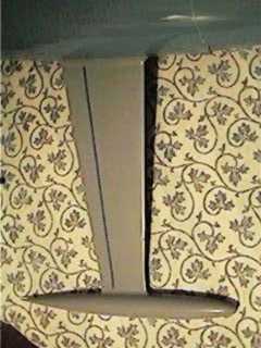
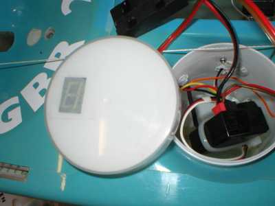
Lester Gilbert on RMG Digital Voltage Display
I've acquired one of Rob Guyatt's "flash" units (an RMG Digital Voltage Display) and installed it in the lid of my pot. It works perfectly, and makes for an altogether more relaxed day of sailing.
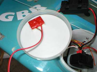
It is quite simple to cut a rectangle into the lining of the SAILSetc pot lid, and then to fasten the flash unit to the inside of the lid with a strip of double-sided sticky-backed tape.
(2006-07-11
©2008 Lester Gilbert
Lester Gilber on varying the gap between the jib foot and the deck
http://www.onemetre.net/Design/WindHanJibDeck/WindHanDeck.htm
Lester Gilbert on boat balance
For any given hull/rig combination, Graham Bantock feels the degree of weather helm is dictated by three basic factors:
* mast rake/mast position
* relative twist in main and jib
* relative sheeting angle of main and jib
with the minor factors:
* relative camber of main and jib
* relative shape of main and jib.
He goes on to say:
There is a fairly small range of successful pairings of twist and sheeting angle. The sheeting angle ranges are covered by the range 8 to 15 degrees for the jib, and 2 to 8 degrees for the main. Keep the twist in the sails so they look much the same from astern. Use mast rake/mast position and relative sheet angle to tune the balance. Use sail camber primarily as a throttle - fairly flat in very light airs, fuller as wind speed increases up to the point where you need to keep the boat more upright for best speed and pointing when you flatten sharply. Camber can also be used to adjust the helm of the boat. Experiment.
As far as I can tell, my Ikon and Italiko tune up just like any other IOM, the major issue being to get their balance right -- ie, appropriate weather helm. So far, I've found both work best for me with a touch of weather helm, that is, when they reliably round up into the wind rather than sailing "neutrally" with my finger off the rudder stick. If you have your rudder trim calibrated, I'd suggest going for that amount of mast rake which gives you about 2 or 3 degrees of weather helm as the "ideal".
As an aside, some sailors feel that mast rake does other things for you, perhaps improving the lift characteristics if the mast is raked well back to give some sort of "sweepback". As far as I can see, mast rake in an IOM is exclusively concerned with boat balance and helm, and has negligible other effects on any other characteristics of the boat.
There is an aspect of helm that has puzzled me for quite a while, and that is the phenomenon called "snap" weather helm. This happens when an otherwise well-behaved boat luffs violently into wind when a puff hits, and I had this problem with my Ikon. When I started sailing my Italiko and until recently, I never encountered it, and began thinking that snap weather helm might be a characteristic of hull shape. I realised I was wrong about hull shape when my Italiko snapped back at me, and I spent a little time investigating. It now seems to me that I had inadequate rig tune.
2006-07-11
©2008 Lester Gilbert
Lester Gilbert on winch drum's and winching
I've had two kinds of winch drum turned in my efforts to fine-tune the response of my RMG-380 sail winch at close-hauled. The RMG-380 (and, for the IOM class, the more appropriate RMG-280) has outstanding power and speed. I have my mainsheet post as low down as possible, and deliberately use the power of the RMG to "sheet vang" -- tighten the leech of the main at close-hauled when I want to. Please DON'T try this with a Whirlwind, Futaba, HiTec, or ANY other winch! I also have absolute confidence in the ability of the RMG to sheet in from a broad reach to close-hauled when the wind is right at the top of "A" rig within an instant. In fact, I've broken my servo tray proving it can do this. But the resolution and repeatability of the RMG at just off close-hauled is not wonderful.
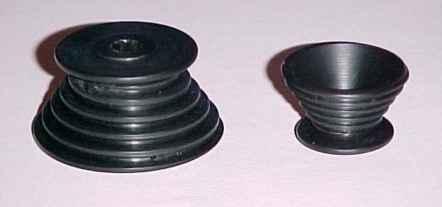
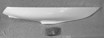
Snail drum
The 8-bit analogue to digital converter of the RMG controller electronics provides for 255 separate positions of the drum over its travel of around 5 revolutions. If we call this a round 250 positions, we get 50 positions per revolution. If the drum diameter is, say, 28mm, then one revolution pays out about 90mm of line, or about 1.8mm per position.
The problem is, although the theoretical resolution is1.8mm, repeatability is about twice this value, around 3.6mm, and at close-hauled 3.6mm is a very significant difference. The winch electronics cannot (at present) do better. So it is necessary to have a drum whose diameter is less at close-hauled. The first picture illustrates two "snail" drums, which have an ever-changing drum "diameter". The larger drum, shown upside-down, has a total travel of about 600mm, and the smaller drum has about 300mm. (You may need to turn up your screen brightness to see the detail clearly. These black, shiny things are very difficult to photograph well.) The smaller drum has a maximum diameter of about 28mm, down to about 12mm close-hauled. One revolution at close-hauled pays out about 40mm, so resolution is about 0.8mm per position, and repeatability is about 1.6mm.
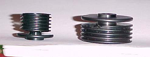
Step-down drums
The second picture illustrates two "step-down" drums. These drums have two diameters, a larger diameter, and a smaller diameter. The larger of the step-down drums illustrated (again, upside-down) has a total travel of about 550mm, through four turns at the 32mm larger diameter, and any remaining turns at the 12mm smaller diameter. For all of these drums, the sheeting line is tied through a small hole in the drum at the fully sheeted-out position, at the largest diameter of the drum just where the channel starts.
Your friendly lathe operator should be able to turn one of these drums for you to try. I understand that it is an exacting and time-consuming process, though, so be sure he owes you a favour first; it would be rather expensive if you were to be charged full commercial rates. Alternatively, Rob Guyatt now sells excellent examples of these drums to suit his RMG winches, in three diameters, at exceptionally good prices. What are you waiting for?
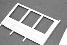
Closed-loop sheeting arrangement
Naturally, neither of these kinds of drum can be used in a "closed-loop" system, but I've not found that to be a drawback. In fact, just the opposite; if the sheeting line is tied to the drum so that it is fully sheeted out on the run with absolutely no more line around the drum, then should the line jump off the drum at any time, sheeting right out and then sheeting back in again always clears the problem. The diagrams illustrate the two main methods of sheeting from the winch drum -- closed-loop or open loop -- and an arrangement of the sheets.
Open loop sheeting arrangement
The "Drums" spreadsheet (about 16kb) makes some simple calculations relating to sheeting and drum turns. Given the main boom sheeting angle and the sheet attachment point, the line run is calculated. Then the number of turns needed for each type of drum to sheet that amount of line is calculated. For a "simple" drum, the number of turns is calculated straightforwardly. For a "snail" and a "step-down" drum, given the maximum and minimum drum diameter, you enter trial values for the number of turns until the calculated wind is about the same as the expected line run. Alternatively, the revised spreadsheet has some macro buttons you can click. (Note that the presence of the macros may trigger an anti-virus alarm in your system.)
Sheeting lines arrangement
A final comment concerns getting to use the small amounts of sheeting required by "sheet vanging". Normally, it would be rather tricky to be able to move the Tx winch stick by, say, 1/50th of its travel, never mind 1/250th, and some skippers wonder whether the fuss with these drums is worth it. I use a Futaba 3VC computer radio (which can command the Rx to 1/1024th of full-scale travel at highest resolution) and have "exponential" travel on the winch stick, such that one "click" on the stick, 1/20th of the stick travel, gives me about 1/150th of travel at the winch. Another click gives me about a further 1/80th of travel at the winch. I thus have three winch settings which I use at close-hauled, corresponding to pinching, normal, and footing, with three different amounts of twist pulled into the mainsail and just a small change in sheeting angle.
2006-07-11
©2008 Lester Gilbert
Lester Gilbert on Boat weight and Boat speed
http://www.onemetre.net/Build/Accel/Accel2.htm
Monday, June 30, 2008
John Fisher | finished up another star today, 842

I finished up another star today, 842. It has the 1" extra Fb ( free board) in the bow. It seems to sail well, it did not make as much difference as I expected. Still was able to bury the bow in a puff and the rail still gets put under when hard pressed.
Going to take it to TX this weekend and see how it compares. If it works well I will post the offsets and frames, if it doesn't work, will post the results.
You can also see the radio pot on the deck. I added this in expectation of sailing in salt water. It is a rubber maid screw top container, 4 for $3.50 at your local grocery store. Even has a flange so you can bolt it down.
Tuesday, March 04, 2008
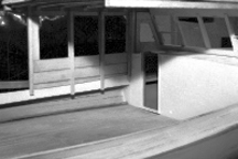
Beals Island Maine - Model Boat Show - ExploreNewEngland.com
''If I'd been born 50 years ago, I'd have been a boat builder,' said Smith, a descendant of island settler Mainwaring Beal Jr.
Smith spent much of his childhood watching fishing boats being built in local shops. The old-time wooden-boat builders and their distinctive designs and construction methods made a big impression. ''I get the lines out of my head. It's all by eye,' he said of his model work."
Library the Beals Historical Society - Jonesport, Beals Maine hitsorical society, museum, library
Saturday, June 02, 2007
Monday, January 22, 2007
Wooden Canoe Journal - Issue #108
Issue #108 - December 2001 - Volume 24 Number 6
FEATURES
* Pierre Trudeau's Canoe Featured in One of Two New Canadian Canoe Museum Exhibits
* Dave Baker 1941-2001
o by Jack McGreivey
* A Remembrance of My Father
o by Todd Baker
* A Master Craft Man
o by Fred LeBrun
* Canoe or Kayak?
o by Patty MacLeish
* Building a Quarter Scale Model of an Algonkin Hunter
o by Arnie Spielbauer"
Wednesday, July 05, 2006
Making a keel mold
I made a plug from balsa and finished it to a smooth finish second I used two aluminum pans (the kind that you throw away) I filled the first one with plaster took the bulb (well waxed) and placed it in the plaster half way in I used two pins through the center to hold it down. let that dry then pull out the plug next put thin saran wrap over the mold and place the plug back in the hole.
Now comes the fun part I used rubber bands to hold the plug in place (remember I had two pins that extend past the mold walls) next fill the second pan with plaster and lay the first on top it is kind of messy but it works. When the second half dries (about two hours) pull them apart. You will need to plug the holes at the ends on the sides and create small air path upward in the and a spur (looks like a funnel when you
are dune this needs to be big enough to pour in the led) at the end.