http://www.onemetre.net/Design/Twist/twist.htm
Given a wind gradient, and given the way the jib deflects the wind over the main to put it into a header, what sort of twist needs to be applied to the sails to optimise their entry angles?
I've come up with a second twist spreadsheet (about 27kb), which takes the earlier "gradient" and "apparent wind" spreadsheets and combines them with new material on "equivalent angle of attack" of arc-section plates, and on downwash. It's pretty! If you'd like to continue, I'd suggest printing this page, then downloading and running the spreadsheet. You'll need to cross-reference quite often.
UPDATE: A fourth version of the spreadsheet, now twist & downwash, here.
The first part of the spreadsheet allows you to specify the sailing conditions (wind strength, wave size, bearing, boat speed -- see the wind gradient and apparent wind pages for more details) and your boat setup (sail chords, draft, max draft location -- see the entry and exit page for more details). Then the interesting stuff begins.
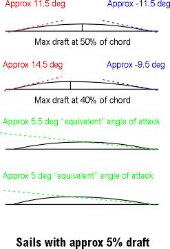
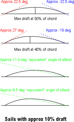
We can start by noting that the red lines represent the "entry" angle of the luff to the wind, and the blue lines represent the "exit" angles. If we assume our sails have an arc-of-circle cross-section (yeah, I know, not a wonderful assumption, but it'll do to highlight the main points), then the entry and exit angles for a sail with max draft at 50% of chord are the same and are equal to 4*ArcTan(draft%). If the sail has max draft at another location, my spreadsheet breaks the arc down into two circular part-arcs, a forward part and an aft part, and calculates from there.
Now, the key at this point is that if these sails were rigid and were sailing off the left hand side of the page, they would generate a fair amount of lift, even though their angle of attack, measured at their chord, is zero degrees. I took a couple of interesting days digging through the NACA archives and I was rewarded with grand-daddy Prandtl (references in the spreadsheet) telling me that these sails develop the same amount of lift as a flat plate inclined at a tangent to the three-quarter chord. Now the tangent at three-quarter chord is none other than the line connecting the leech with the point of maximum draft, as illustrated by the green lines.
Entry, exit, attack for 10% draft Entry, exit, attack for 5% draft
Our 10% draft sail with max draft at 50% is running at an "equivalent" angle of attack of about 11.5 degrees. Move max draft forward some, to 40% say, and the "equivalent" angle of attack reduces slightly to about 9.5 degrees. Another way to look at these numbers is to say that the angle of attack of zero lift, which we'll need in a little while, is -11.5 and -9.5 degrees respectively. Of course, our sails get nowhere near negative angles of attack, they just luff out, but the general idea applies just as long as they are filled and driving. Here is another set of diagrams, but with a 5% draft sail.
Very roughly, take half the draft, and you end up taking pretty much half of all the other figures as well: entry, exit, and "equivalent" angle of attack/angle of attack at zero lift.
(As an aside, the NACA archive was fascinating. In about 15 years from 1905, ie from the Wright brothers, pretty much the whole of aeronautics had in principle been cracked. Prandtl could write a report in 1921 to which the rest of this century really just added footnotes. Amazing. Now we've been sailing for thousands of years, and there is nothing remotely comparable. Great! There is so much yet to know!)
OK. Now it's time to set our sail as a jib. We'll sheet it at 15 degrees to an apparent wind about 30 degrees off the bows, pretty much a standard sheeting angle for an IOM. The 10% draft sail illustrated (which has max draft at 40% of chord) seems to be unhappy at this sheeting angle. While it is making an acceptable "equivalent" angle of attack of about 22.5 degrees to the apparent wind, it is showing a very poor entry angle of around -13 degrees, and really could not hold this point of sailing at all. She'd luff and the boat would have to bear off. Also the exit angle shows the leech somewhat hooked over the centre line.
The 5% draft sail is showing a much better time of it, and can clearly point in the situation we are analysing. The "equivalent" angle of attack is less at about 17.5 degrees, and so the sail will develop less lift than the 10% draft, but the entry angle is nearly perfect -- exactly into the wind -- and the exit angle is good as well, just off the centre line.
Jib Main
So our 5% draft sail seems to be able to point 10 to 15 degrees higher than our 10% draft sail. But you knew that a flatter sail could point higher, didn't you? (In fact, the 5% sail can only point about 3 to 5 degrees higher than the 10% sail, not quite the full 10 or 15 we might have imagined. I'm still working on the reasons for this...) The old salts will tell us that a flat sail doesn't develop as much power, and they'd be right I guess. The maximum coefficient of lift of the 5% sail is about 1.1 at a nominal angle of attack of, say, 11 degrees to the apparent wind, while for the 10% sail it is more like 1.5 at an nominal angle of attack of about 15 degrees. The power developed by a sail is pretty much a direct function of its angle of attack (assuming, of course, the sail hasn't luffed or stalled). In a very real sense, the "only" purpose of a nicely shaped aerofoil (ie a sail) is to allow that aerofoil to achieve a maximum angle of attack. The "only" reason a flat plate isn't a wonderful sail is that it can't achieve much of a useful angle of attack. The 10% draft sail gives us about another 4 degrees of angle of attack over the 5% sail before she stalls, and hence gives us more power, but at the expense of not being able to point as high. On the reach, I'll take the 10% sail please. On the beat, though, pointing ability is more important, so give me the 5% sail.
We are not knocking 10% draft sails. We are just showing how the analysis so far, particularly from looking at the entry angle, indicates they can't point. I sailed a regatta a few years ago with a dog of a boat, and amazingly did well. The reason, I now realise, is that the course was a long rectangle, laid across the wind, so there was only one short beat but two long reaches. What I lost on the beat through lack of pointing I more than made up on the reach with a very full sail set.
Downwash
The next thing to do is to look at the situation with our mainsail. Before we do that, though, we have to remember that it is the downwash off the jib that puts the main into a header, and allows the main to be sheeted more closely to the centre line. So exactly how much is this downwash?
Another trip through the NACA archives revealed another grand-daddy, Munk (reference in spreadsheet), who trailed streamers behind a wing in a wind tunnel and measured the downwash. Thankfully, he wasn't shy about saying straight out that, over the centre section of the wing (we know vortices twirl up at the ends and mess things up there), downwash was pretty much the angle of attack divided by 1.8. Excellent. (If you've ever read any of these NACA reports, you'll know they are stuffed with the most excruciatingly difficult mathematics, whose real-world application to the job at hand is often dismissed with a wave of the hand and "It's obvious that..."!) Our jib at an "equivalent" angle of attack of 22 or so degrees to the wind will generate about 12 degrees of downwash. The main is now sailing into an apparent wind, 30 degrees at the jib, now deflected to about 18 degrees to the centre line. This was why we had to get straight about the "equivalent" angle of attack, because downwash starts much sooner that that indicated by using the boom or chord as the measure of angle of attack. It starts from the angle of "zero lift", which for our sails is (theoretically) something like -10 or -11 degrees.
We'll sheet our main at 5 degrees off the centre line, again a pretty standard setting for an IOM. Given that we now realise we are making our boat point high if not actually pinch, we can see how the 5% draft sail again handles the job rather nicely. The entry angle is pretty much bang into wind, and there is a good "equivalent" angle of attack of 19.5 degrees. Interestingly, the leech seems a little hooked, but according to the current analysis that's actually just fine.
Lift coeff distribution
So far, we have been taking a 2D sectional view of our sails. To progress, we now have to apply these ideas to the sails in 3D. The next step is to ask how the downwash is distributed across our jib. It is good to know what it is in the middle -- Munk told us about 0.56 times "effective" angle of attack -- but it is also pretty important to know what it is at the foot and at the head.
The graphs are what Tom Speer's VORTEX95 spreadsheet told me. I still don't fully understand the spreadsheet, but I think it is saying that downwash picks up from the foot and increases towards the head for a triangular sail, and it isn't nicely constant like Munk found with his better-behaved wings. Well, that's what I've taken it to say, so in my spreadsheet I've taken some points off the graph which correspond to the batten positions on the jib and main, to represent the downwash being generated at those positions. I wasn't too confident about the values of downwash at the foot, which the graph says are pretty negligible, so I've fudged here a little, and pretty much made the whole downwash distributions linear for the spreadsheet. Hey, the fun of this is, if you don't like my numbers, you get to put your own in.
As an aside, VORTEX95 also gives a very neat picture of the lift distributions for a triangular sail. One graph is the distribution of the lift coefficient -- the measure of how hard the sail is working to produce lift, everything else being equal. Once it has picked itself up from 0 at the foot, it gives a reasonably straight line -- a pretty even distribution of the lift coefficient which, as everyone knows, is what characterises an elliptical wing and must therefore be A Good Thing -- from about one third of luff until it drops away again right at the head.
The last graph shows the actual amount of lift force being produced by the sail, and pretty clearly it is the bottom third of the sail which produces the most force, due of course to there being more sail area down there. If you'd like to reproduce them, these graphs were obtained with VORTEX95 by putting in a triangular planform on the "Analysis" tab, setting the angle of attack at 16, and twisting the head off -8. Now if there is anyone out there who can really explain the downwash distribution to me, I'd be more than very pleased to hear from you...
So, the spreadsheet accounts for the jib downwash acting on the main by assuming that the jib downwash is, first, 0.56 of the jib "equivalent" angle of attack, and then that it is stronger at the head and weaker at the foot according to the points picked off from the theoretical downwash distribution, as per the graph above.
Lift distribution
Finally, we get the point of the exercise: how this affects the twist to put into the jib and main. Twist is needed for two reasons. First, the wind gradient. The spreadsheet estimates this gradient and suggests what values of twist would match it. But second there is the much more vexed question of the induced upwash at the luff (discussed on the circulation page). The luff upwash is really the complement of the sail's downwash. The more lift the sail generates (ie the higher the angle of attack), the stronger the downwash at the leech, but also the stronger the induced upwash at the luff. This is important because the sail will start stalling (starting from the head). As the induced upwash increases, the "effective" angle of attack of the sail increases, unless steps are taken to lower its angle of attack. So the twist we want to put into the sail is to lower its "effective" angle of attack to something "reasonable" so that if it is to stall, it stalls along the whole length of the luff nearly simultaneously. We don't want it to stall at all, of course, so what we are really doing is ensuring maximum drive from the sail over its entire luff by twisting the head off "sufficiently".
The best I could do on my final foray into the NACA archives was to try and make sense of Millikan, who was the only author I could find to talk about "self-induced" downwash (reference in spreadsheet). I'm on very shaky ground here because the formula he offered seems to be clearly in error to me, and so I've taken from him as the fudgiest of fudge factors a simple function of eta, the wing "efficiency". It turns out that this fudge factor is about 0.62 -- take the downwash, multiply by 0.62 or so, and we just might have the induced upwash at the luff. So the spreadsheet calculates the induced upwash as 0.62 of the downwash, and suggests this as the amount of twist that would "accommodate" the induced upwash so the head doesn't stall. All right, it ain't perfick (as Pop Larkin would say) but it'll have to do for now. Don't like it? Pop your own number in there for eta, something between 0 and 1 will do nicely...
(On the side, there is one more thing. We've been talking here as though the sails were bolt upright, but of course they aren't. Start blowing on them, and they'll heel. Oh, they say, that's just lots of dihedral and maybe just a little sweepback, so nothing really changes aerodynamically except that the forces go down in magnitude, and the vortices just slide off the sail head a little more smoothly. I sure hope so.)
So what do you find when you start playing with the spreadsheet? Well, try setting jib and main twists to the recommendations. You'll need to do this for a couple of iterations, because when you enter the "actual" twists, the "accommodating" twists change for induced upwash to reflect the new values. But it soon settles down. You might not like what you see, particularly on entry angles, so it's then time to sheet out or in, close the slot or increase the slot, bear away or point up, change the sail draft or position of max draft, swap to No.2 rig, and all sorts of things. You're off!
As for me, I've now properly understood how changing the sail draft from the foot to the head (ie the broadseaming at the seams) builds twist into a sail that otherwise can't actually have twist sewn "directly" into it.
Next year, I hope to get into biplane theory and nail down the old chestnut -- should the jib sheet out equally to the main on the reach? We're talking about the simultaneous change of stagger, gap, and decalage here; wonderful stuff! (Sneak preview -- results so far suggest the jib does still need to sheet out just a few degrees more than the main, but not a lot...)
2007-08-12


